Old iron, it is perhaps one of the last resources of value in machinery left to the average craftsman that is both affordable and desirable. Consider this about machinery built in the 40s, 50s and 60s; the skilled tool makers who plied their trade for well established companies were proud of their abilities, and wide- ranging in their knowledge by having come up through the ranks under the tutelage of precise, accurate, and respected craftsmen before them. These are the guys who became our arsenal of democracy during the war years and who only knew how to build things one way; as if someones life depended on it working perfectly every time. By the end of that era, when marketing took a different direction and these old hands retired or died off, new criteria was established that allowed for only a small portion of craftsmanship to be invested in a product, and thus the throwaway movement began. It was my good fortune to have once known some of these very craftsmen, and so I feel inspired to do the forensics to restore, reuse, and enjoy tools so nearly perfected that they could be brought back to useful life even if left abandoned in a corn field for decades. What follows is one such story.
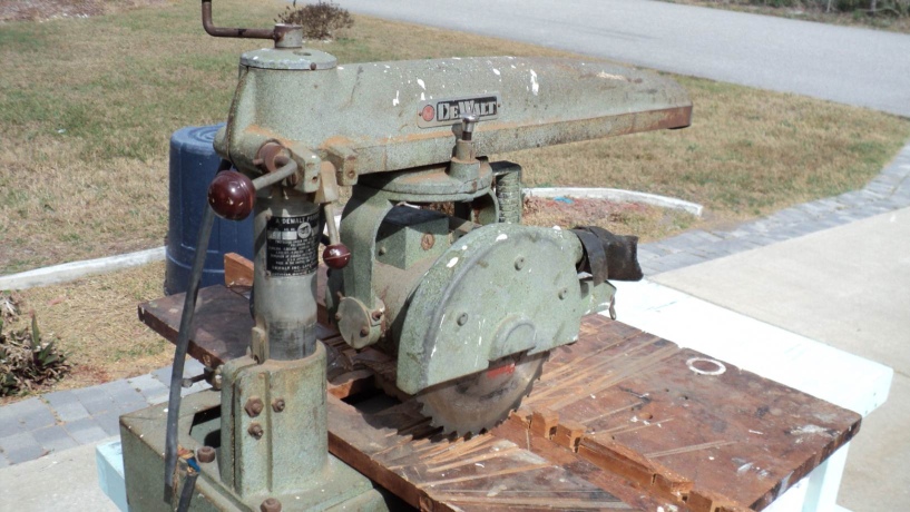
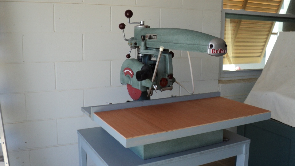
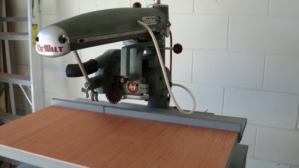
Once brought home, the initial inspection shows a saw that hasn't seen a knowledgeable, caring operator for decades, yet what remains is still very useable.
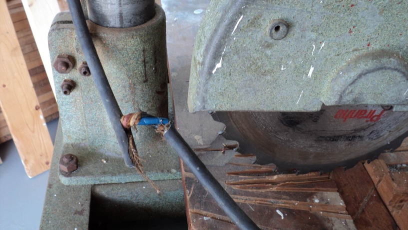
This is something you don't want to happen to your saw. Apparently the power cord was left in the line of cut and was blunderingly severed at some point.
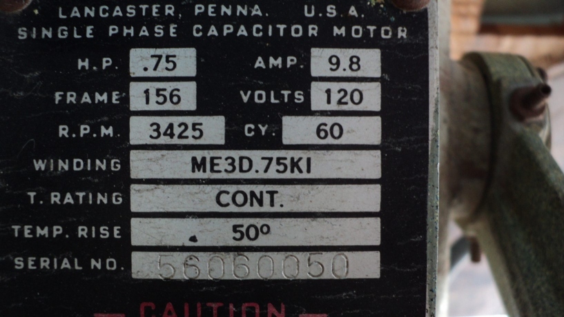
The motor serial number tells me this saw was manufactured in June of 1956- 56 (year) 06 (month) 0050 (sequence).
Things that happened during that month and year were:

As is my usual protocol, when subassemblies were dismantled, images are taken of parts in order of relative position, this aids greatly when reassembling. More details can be had in another document that shows just what lengths I go to concerning rebuilds- Meet My Sweethearts.
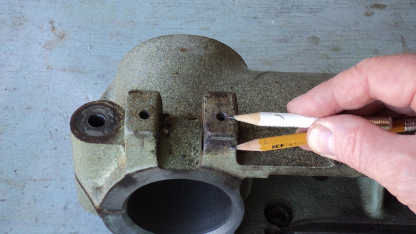
I really ran into a brick wall when trying to remove one of the two index pawl's locking screws. It was a 1/4- 20 socket setscrew frozen in place (white pencil) and resisted all my efforts to free it. At one point I was considering abandoning it and tapping a new one below it (yellow pencil), but at the last minute I decided to try and bore out the hardened screw with a Tapcon's carbide- tipped bit of 5/32", that did the trick and there was no thread damage either, so I'm happy it's still in an as manufactured condition.
.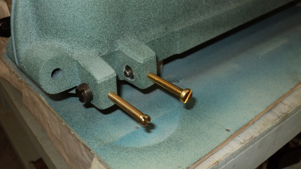
I wanted to replace the old system of locking setscrews that was a complicated pairing of a steel Allen socket setscrew that would bear against a tiny, loose brass disc (to prevent main screw thread galling). Using stock brass screws I began the refinement process to make them look more professional, starting with turning the head down to a minimum diameter.
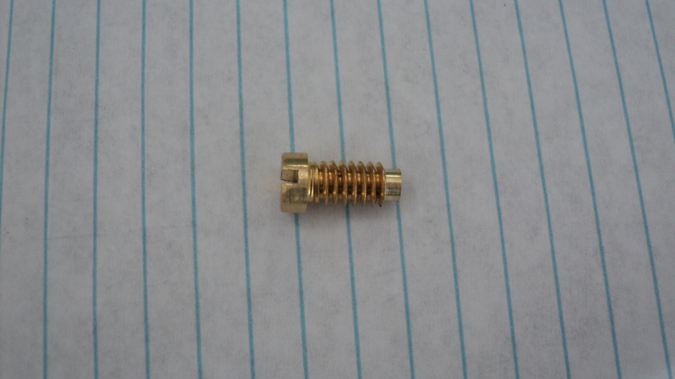
After determining final length I dog pointed the screw nose so that if it deformed against the thread it would still back out easily enough.
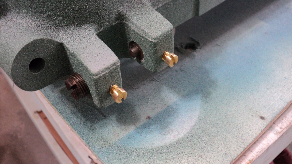
They worked as expected, their function is obvious, and they look like they belong too, something I wasn't about to compromise on after my struggle with the recalcitrant screw.
After all the above was completed, it was time to prep the surfaces for refinishing. This was not hard at all since after more than a half- century of age, the paint was flaking and peeling off just about every surface. I used simple tools like a wire brush, scraper, steel wool to do the mechanical stripping, then a wash with T.S.P. followed by a water rinse, and that's it.
Primer: Rust-Oleum Gray Metal Primer
Top Coat: Rust-Oleum 239119 Multi-Color Textured Spray, Sea Green, 12-Ounce
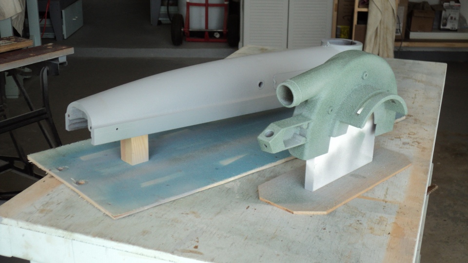
It's worthwhile if you take some time to make custom support fixtures, it allows you to park the items just about anywhere in the shop without tying up your work benches, and also offers easy handling.
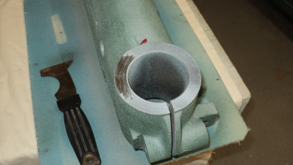
I only masked areas like the badges that were riveted, the carriage lock rail, and a few spots on the yoke. On many areas I just waxed it so that any overspray simply came right up with a light scraping thus saving time, these are rotating surfaces anyway, so a wax residue is beneficial.
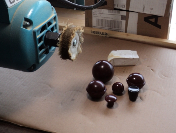
Nothing is too unimportant for a little TLC. Here I'm using the auxiliary output shaft of a DeWalt model 1400 radial saw to polish the control knobs. The box isn't there by happenstance either, the large red knob went bounding down my driveway after I snagged it on the wheel, every operation reveals something needing improvement in the rebuild effort.
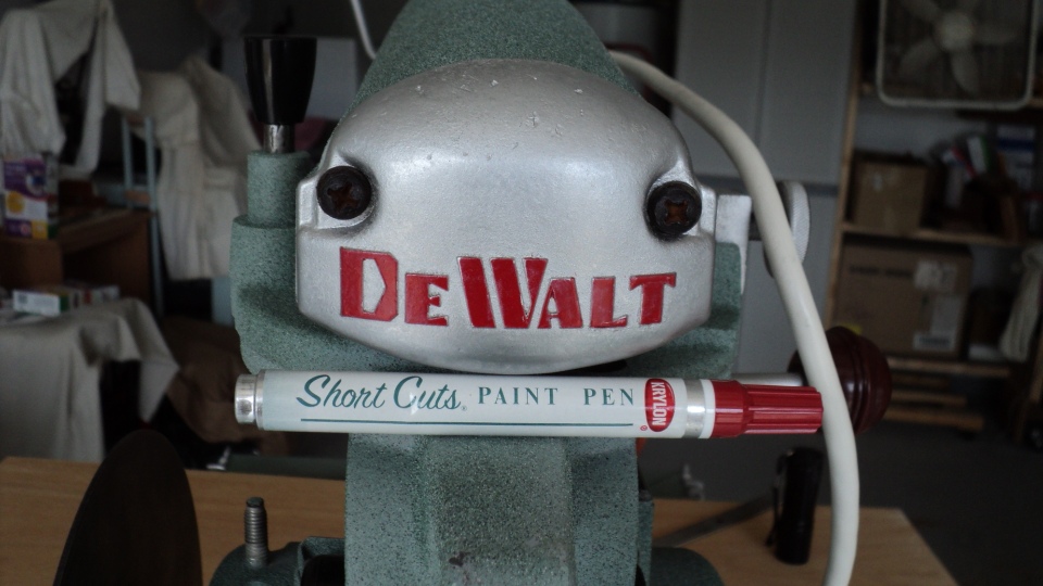
It's the little things that mean a lot, like highlighting cursors and raised lettering, easy enough to do and takes the project up to the next level.
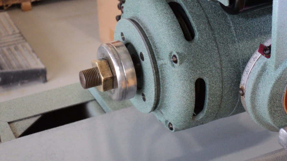
Even the blade washers and Bronze hex nut get the treatment, a rotary wire brush takes off over 50 years of deposits and they come back like new again. Thanks to the quality of plating used on the steel washers they took heavy abrasion that would have destroyed today's minimal 1 micron thick plating.
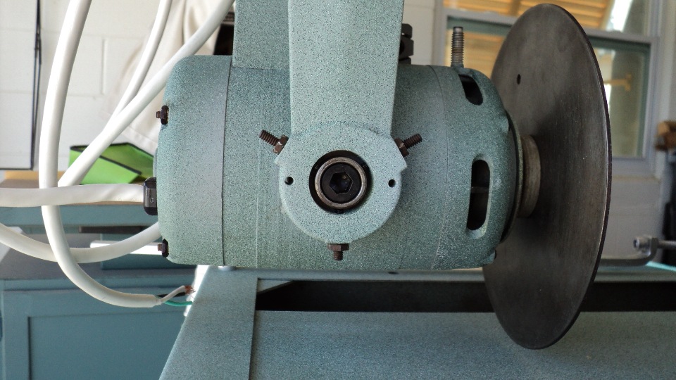
Mounted in the yoke, the newly refurbished motor requires the rear pivot ring to simply be centered by eye to facilitate the rebuild, final adjustment will come later during calibration of horizontal and vertical blade positions. It should be noted the bottom adjustment screw is shorter than the ones at 11:00 and 1:00 so as to not project below the motor body. This flat bottom motor design was fully implemented in 1951 after introduction to prior builds of various models giving what was claimed to be a 40% increase in cutting capacity.
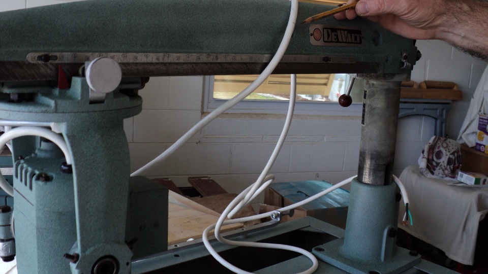
In order to figure out the new length of switched cord for the motor, it is put in the most extreme position and the cord is marked where it will enter the arm bushing, then allowance is given to route it to the power switch, in this case it was 37" total from motor strain relief bushing to end of cord at the switch. Power line cord length is now a matter of personal preference, but when I can I like to make it 10 feet overall.
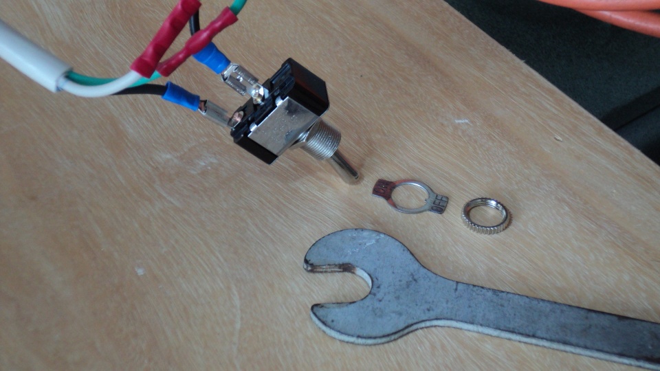
Wiring the power switch is straightforward, I taped the .250 quick connect terminals to protect unwary fingers before mounting it. The arbor shaft wrench just happens to fit the back nut of this switch.
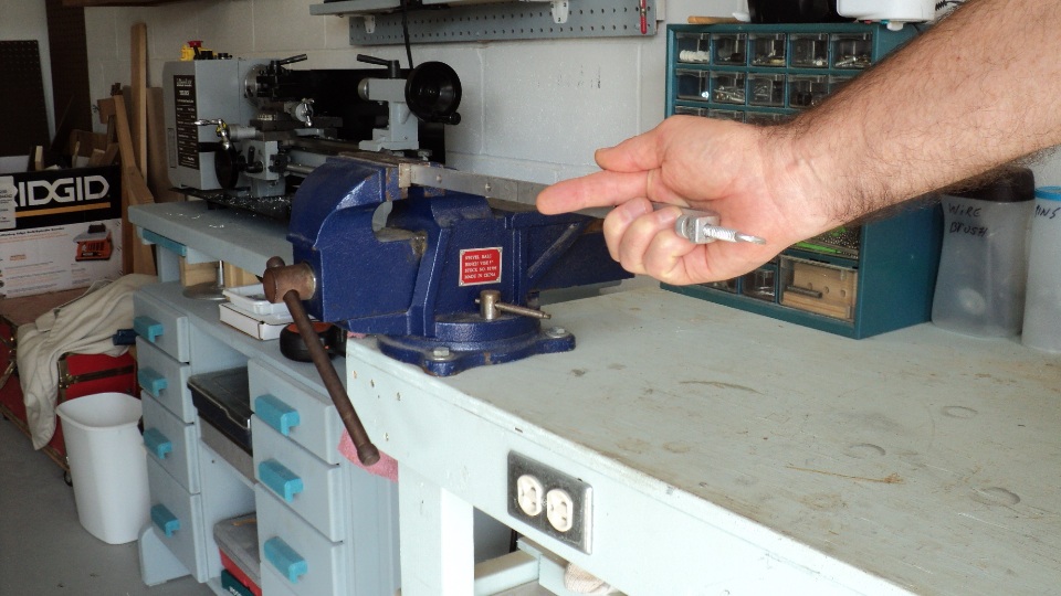
The Table mounting rails needed a little coaxing back into flat, using a bench vise and an "armstrong" fixed that. Since they are made from mild steel, they responded well to this method and no other tools were needed. Finger points in direction this rail is to be bent for correction.
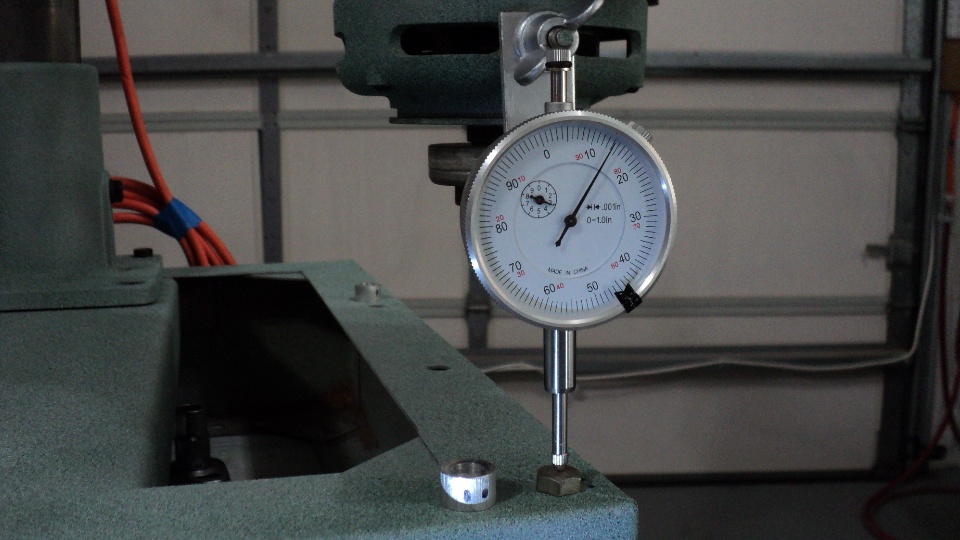
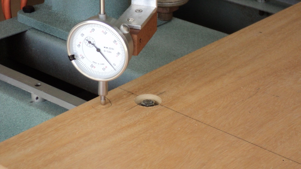
Using a dial indicator and a simple reference point, all 4 base to rail mounting holes were checked for consistency with the arm yoke, and all indicated in at no more than .015" difference, an amazing manufacturing achievement considering 5 or more subassemblies make up the final dimension. Note the 3/8" tall spacer next to the capscrew, if needed I could have customized their height to compensate for variations, but at +- 1/64", why bother?
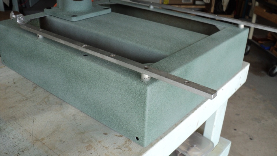
Here the rails are ready to receive the sub table. The main purpose of the spacers is to elevate the rails top surface above the column casting's base flange. This allows the back board pair to extend the full distance behind the rear of the fence and up to the thumb screw clamps.The original design by DeWalt called for a complicated network of hard to do adjustment screws and nuts, I have simplified it to my liking by eliminating as many variables as possible and checking dimensions at every step. The end result is a work surface far beyond what is needed to produce accurate results, and one that by and large will never need adjustment.
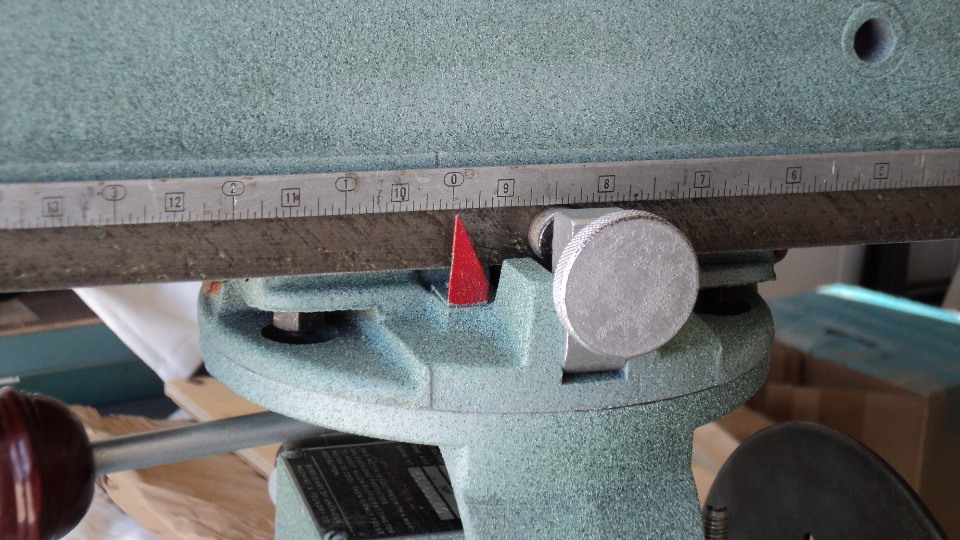
I then centered the rip scale for the in- rip position as that's the one I use the most and will next set the saw's sub table to that reading.
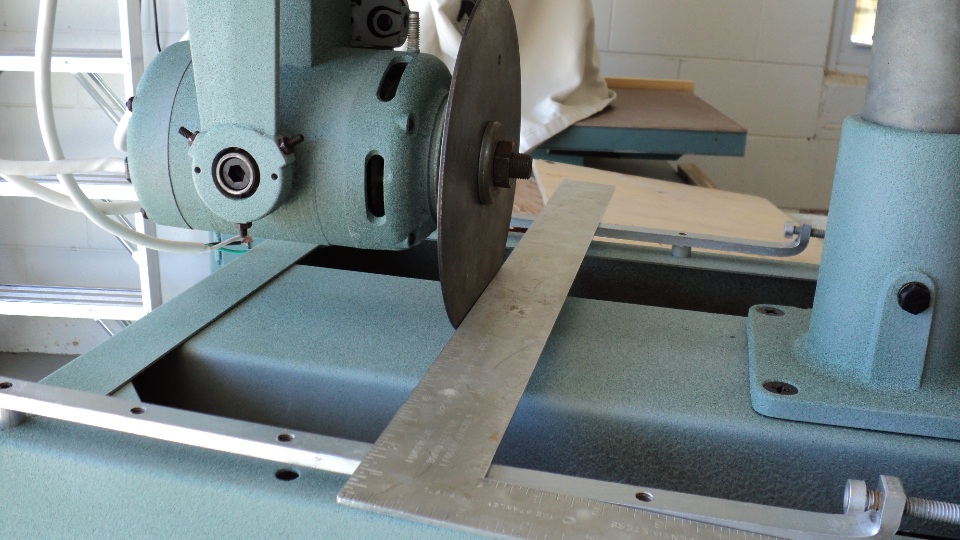
With the above rule scale done, I can now find where the rear edge of my sub table should be simply by locking the motor at "0", in-rip configuration, and placing a straightedge across my setup disk. Note: ensure proper arbor washer order, thickest (3/8") is next to motor face, thinner is outside of blade.
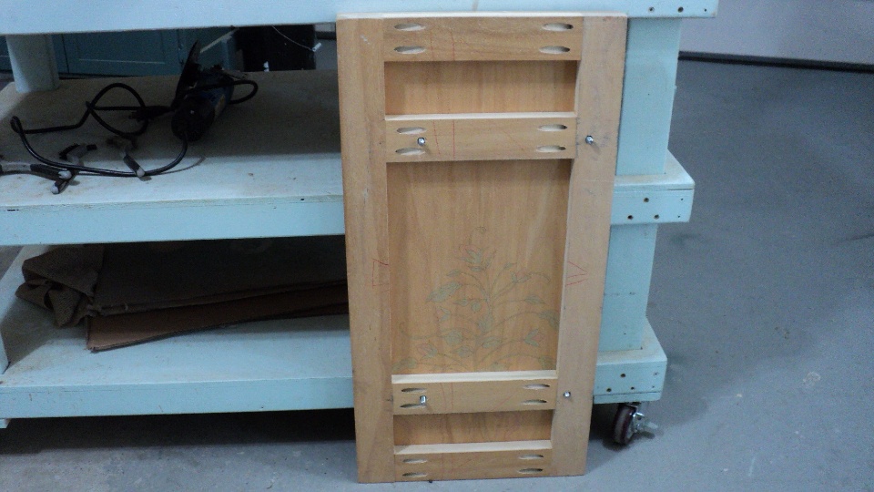
The panel over a grid frame, or torsion box design for the sub table has been my favorite for a long time, having proven itself over and over as being economical, easy to fabricate, and stable in the extreme. There are other choices for fabrication of this part too, and the Mr. Sawdust style is also a good design.
Final check of all 4 extreme corners of the sub table indicated in at less than .005" overall, satisfying the most demanding precision. A sacrificial top of 1/4" Luan or hardboard will finish off this table system, so that when replacement becomes necessary, the flatness will remain for the next lifespan of this saw table.
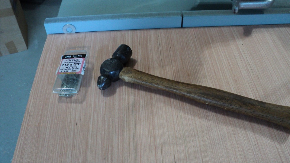
Finally the sacrificial top can be installed. Short brads allow for a thin Luan top that can easily be torn off and replaced when wear and tear have taken it's toll. Note the flat washer sandwiched between the fence and top edge, this sets a sawdust trap that lets debris fall away from the fence for accurate registration of the work against the face of the fence. Top is finished with either shellac or boiled linsed oil for dust control.
When I speak of the value of old iron, I think I hear those long ago craftsmen proudly saying: "It's a tool, use it to do what needs to be done, it wasn't built to be an object of worship, it was built to do a job, do jobs with it.".
I couldn't agree more, and thanks for being an inspirational role model.
Dedicated to my late father- in law, Andrew P.T. O'Brien, Watertown Arsenal machinest, WWII veteran, and Master Model Maker extrodinare.
This Web Page Created with PageBreeze
Free HTML Editor machinist