I picked up a well- used DeWalt MBF radial arm saw early in 2012 and a story about it's restoration is here .
Also included is a link to the nifty shop made press used in this story.
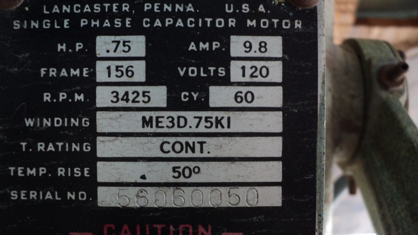
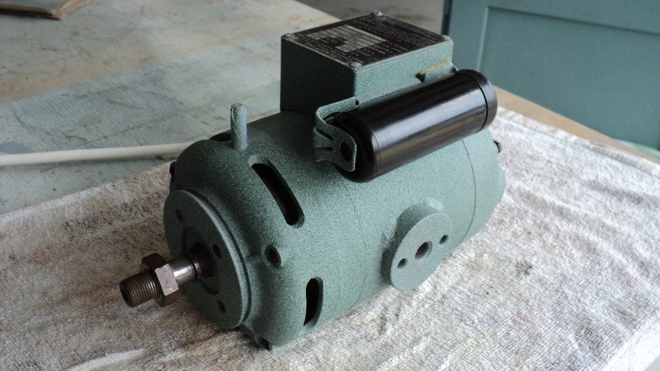
Above, motor badge details.
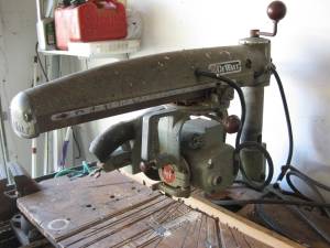
It's gonna be a project alright, can't wait to get her home.
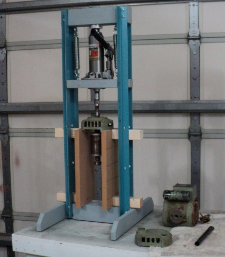
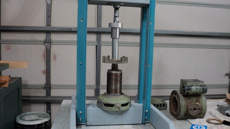
I've always wanted a shop press and this provided the excuse to go ahead and build one as they have other uses as well as motor rework.
First use of the press is to separate the rotor from the arbor end bell. Holding the rotor while cranking the bottle jack, it went smooth, easy, and fast.
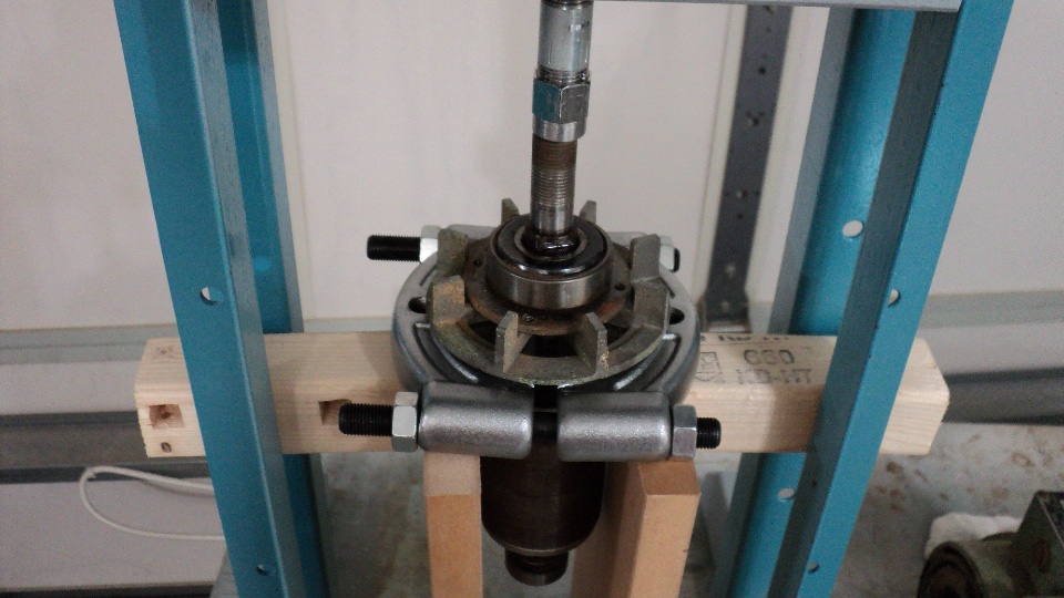
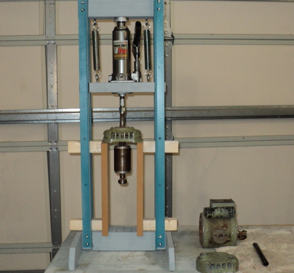
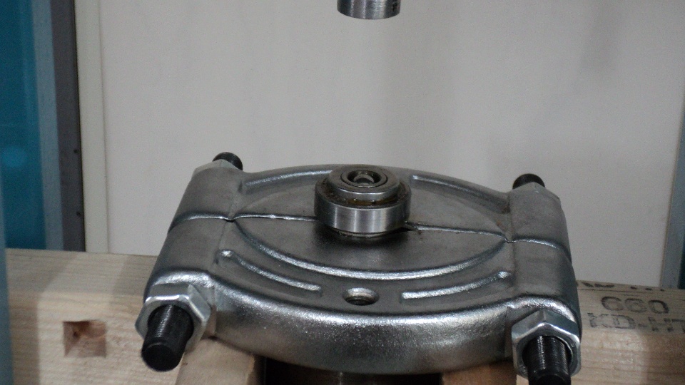
Before using the large collar pair from my Harbour Freight bearing puller set as the main support, I removed the Tru- Arc ring and two shim washers of .003 and .008 in front of the old New Departure bearing. I also deburred the arbor shaft in particular around the wrench flat area for a smooth journey. A shot of P.B. Blast was added and off came the fan, retainer ring and bearing all in one shot. In retrospect I should have positioned the collar so that the gap was supported by the flanking uprights in the 9:00 and 3:00 positions, but nothing untoward happened and that boosted my confidence even more in the use of my press.
It's extremely important to give proper support to the fan hub and not the vanes during removal and replacement, all forces should be focused on the hub and nowhere else.
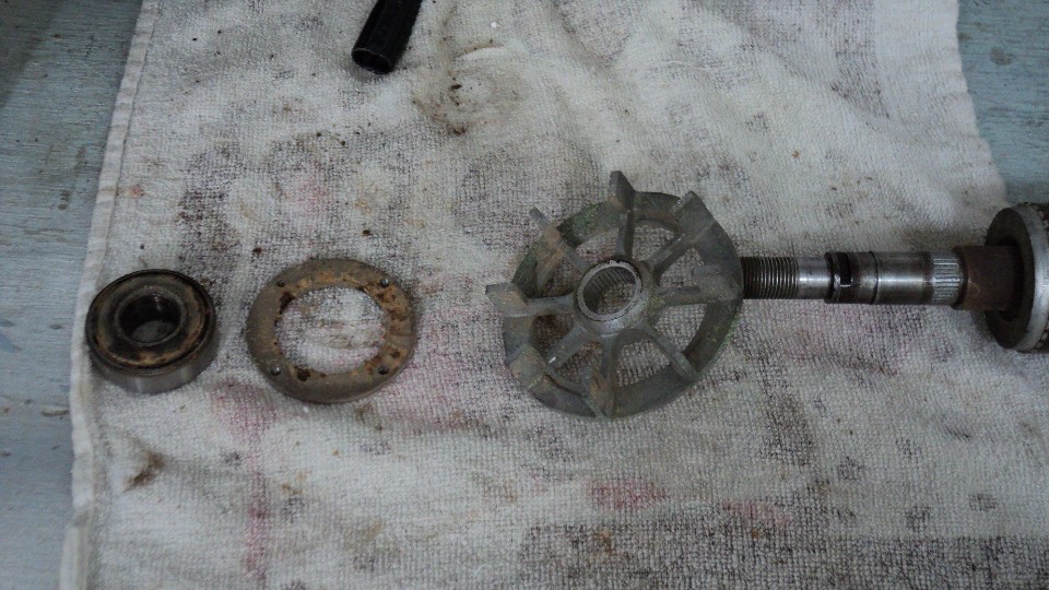
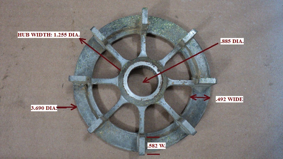
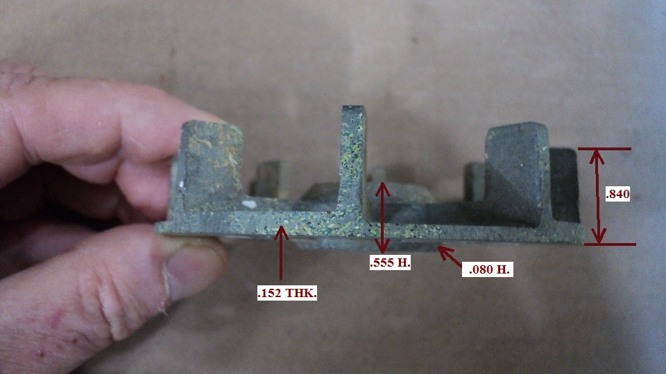
The MBF fan is often a casualty in motor rebuilds, so I took advantage of this opportunity to measure it up for a possible replacement hunt some day. I just have to believe that another fractional horsepower motor exists somewhere that is currently in production that utilizes a fan so similar that slight modification would be all that is necessary to adapt it for use. So here it is, one more for the archives.
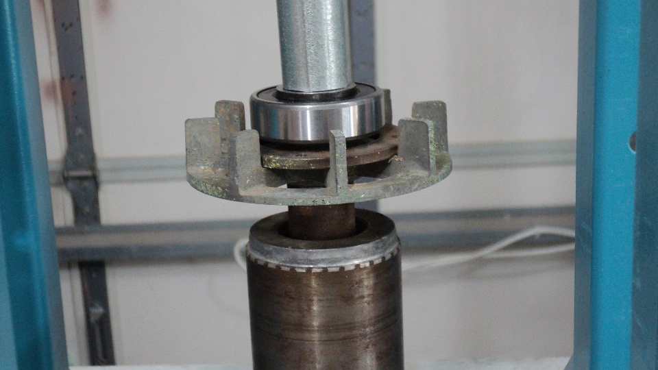
The end bearing came off without incident, I used a small ball bearing as the go- between the ram and centering chamfer at the shaft's end. Here you see proper positioning of the collar device on the flanks. I saved the bearings for some future use by the way, nothing wrong with them in that respect, I just won't put them in a motor again.
Bearings are from Accurate Bearing Co., #88500 for the cord side and #88504 for the arbor side.
The fan goes on first, followed by the retainer ring and main bearing combo. Always work with the force on the inner race, never the outer, this may be accomplished by being creative with short lengths of pipe, sockets, metal flats- whatever it takes to direct the force away from the outer race. Note the use of the arbor end bell as a work support- this helps to ensure a stabile and straight transfer of force.
Visually checking during the press, I ensured it was fully seated before ending the operation- I did not want to use any more force that that which was necessary to do the job.
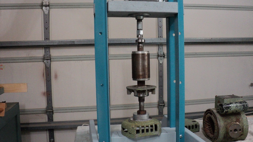
With the rotor turned end for end, the rear bearing is next, and that completes the process. Note the arbor nut is used as a thread protector as well as a foundation plate.
If I had another motor to do I'm confident it wouldn't take more than 15 minutes to swap out the old bearings for new.
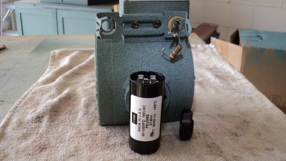
Rewired in the new start capacitor and also the bleeder resistor salvaged from the old capacitor. The end trim cap was also retained for this use as well. This unit is an exact replacement so the fit in the bracket was perfect, other size units may require modifications to mount it.
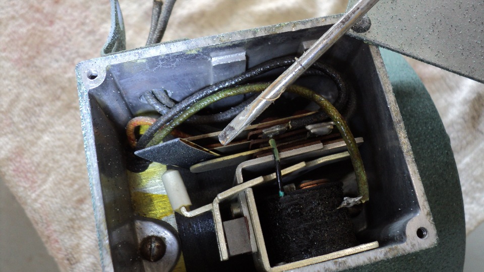
It is also advisable to clean the start relay contacts using 400 grit abrasive sheet. It was folded in half and drawn across the two contact buttons 2- 3 times, object being to only clean oxidation and minor pitting.
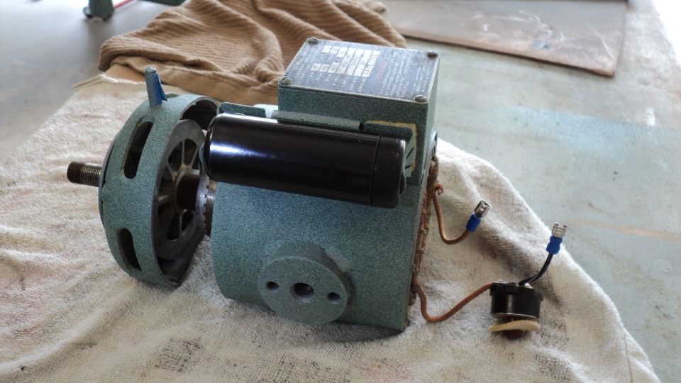
The rotor was pressed back into the arbor end bell and the guard ring screwed into the inner retainer. Quick connects were crimped onto motor leads for easier service in the future if needed.
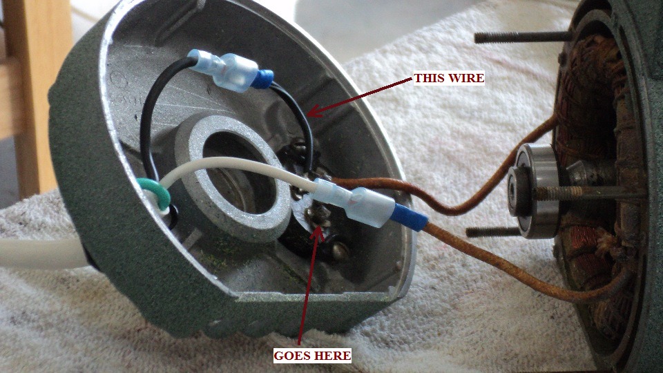
Be certain of using the correct Klixon tab when soldering the connect lead. First run up attempt was no- go, requiring disassembly to resolder it in the proper location.
Here it is, all together and running like a top, click on image for a video.
Now I can remount the motor in the yoke assembly and get on with finishing the MBF rebuild, stay tuned for that story.
This Web Page Created with PageBreezeFree HTML Editor