Some good advice has already been written regarding the setup of radial arm saws, and after restoring and calibrating many tools I use the following procedures that serve me well. There are no great departures from the established principles and this is more a homogenous blend of those methods. A frame 350 motor is used to illustrate key points, but the information shown is applicable to the typical DeWalt saw motors and may be useful in concept to other makes. Use of a dial indicator is quite helpful, and they are inexpensive nowadays. Simple jigs and fixtures can be copied and altered to suit your particulars.
Since the focus is on blade adjustments this tutorial assumes you have already performed the following prior adjustments per their documentation:
-
That all clamps are adjusted for reliable tension forces- adjust as necessary.
-
That carriage to arm roller tension is in the proscribed range.
-
That column motions are fine- tuned, i.e. up/ down, Gib setscrews firm, all unwanted play is gone.
Set The Arm Parallel To Table
Depending on model and vintage, this may be easy or it may be tedious, but be fussy, Mr. Sawdust claims to be in the .005 thousandths range when he made his adjustments. Once done, it rarely if ever needs a revisit.
The following series are the ones most likely to need a redo from time to time, especially if the blade grabs or kicks back unexpectedly. Violent forces are generated and it is no fault of the machine if the settings are knocked out of adjustment. After doing it a few times, the procedures really only take a few minutes to put right the original precision of the saw. It's like an old VW ad used to say about their manual transmissions: "after a while it becomes automatic."
Square The Blade To Table.
The capscrews are behind the bevel indicator badge, loosen, adjust for square, tighten and check once more. Expect some shift as the screws are drawn up- prediction of movement may be called for to compensate and bring the final adjustment to satisfaction
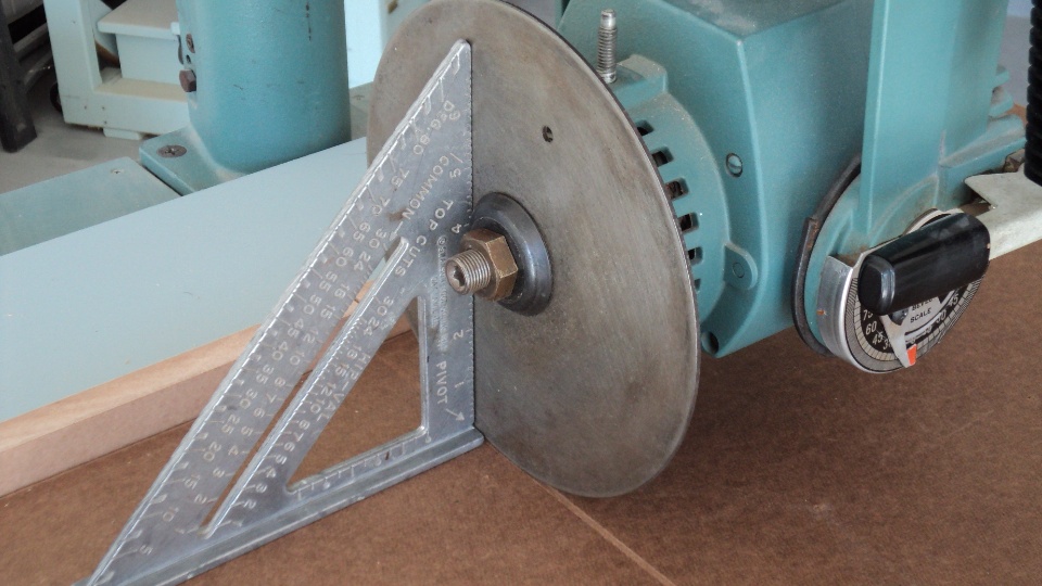
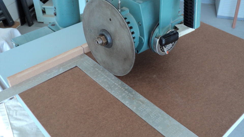
Square The Crosscut
Mr. Sawdust opines that although this may produce a satisfactory crosscut, a precise "meeting of the cuts" can further be had by using a simple verification method - see page 54 of his book for more details.
Horizontal Heel/ Toe
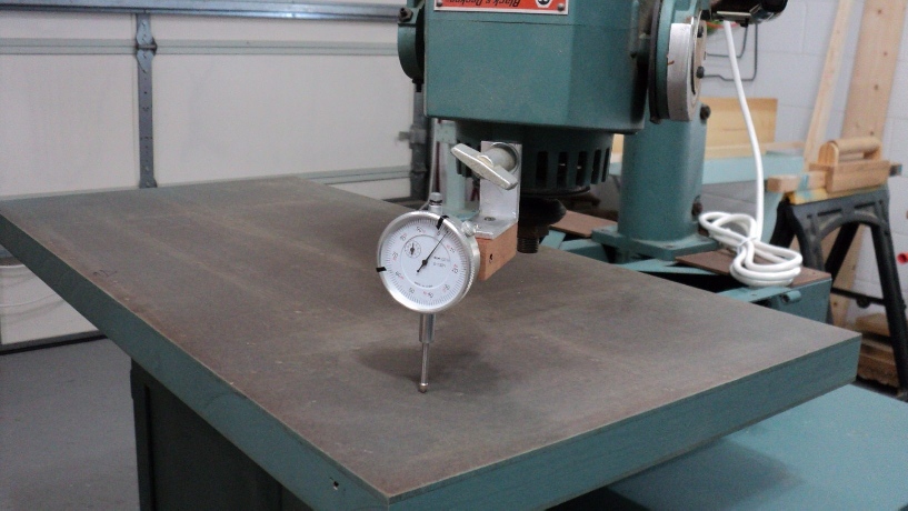
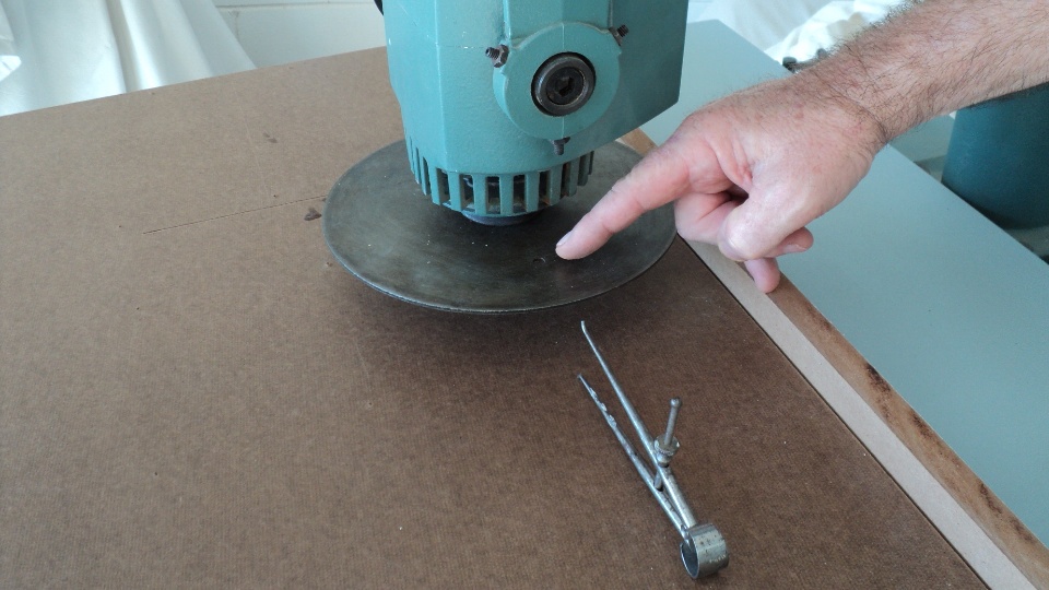
With the motor vertical and the pivoting yoke adjustments to the right, focus is on the bottom screw which will be used for this procedure. Back off all hex jam nuts and take an initial reading with the inside calipers, setting so it just slides under the blade or plate edge- note the head and lower leg form the table top baseline, only the upper leg is moved up or down.
Pick a point of constant reference or make a mark on the plate. Not mandatory, but will nullify any runout. Use the technique for vertical setup as well.
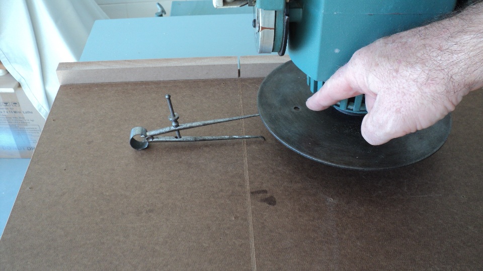
Rotate the plate and check the opposite side, the objective is obviously to have the blade/ plate horizontal with the table surface. Using inside calipers is a very good method for this, as machinists can tell exactness to within one or two thousandths simply by the feel of how much drag the tool sees when slid in and out under the edge. You may have to loosen & finally firm the top two setscrews to allow any adjustment; they will be moved more in the next step, but do not adjust the bottom screw again after this leveling step is complete. Finish by tightening the bottom jam nut.
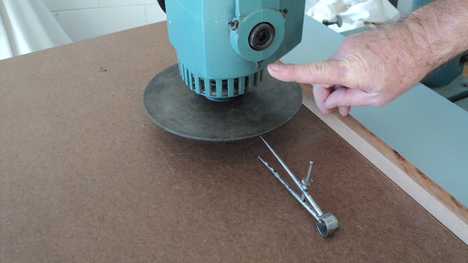
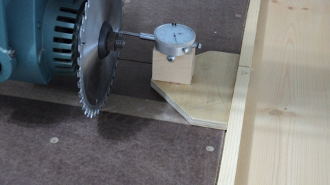
Vertical Heel/ Toe
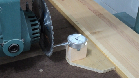
Check for
heel:
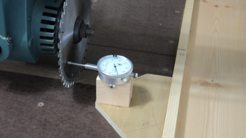
Move to the opposite side, check for toe, these two steps may need repetition. Adjust screws for 0/0 indication. Final step is to ensure all jam nuts are tight
Epilogue
Sequence of events is still important as it is a serial process, every adjustment relies on the previous being correct.