LUX-TX9000 With X10 MS12A Mod
By B. James 2009
Ever had a situation where you needed some kind of X-10 control but had no power line to tie to nor wanted exposed wires? This lets out the Power Flash and any other X-10 Module for this project. Well that was the boat I was in when I wanted to have my Wall Thermostat control a window Air Conditioner.
The Components used in this project were:
· LUX-TX9000 Programmable Thermostat (picked because it had lots of spare room in the case and was powered by 3VDC the same as the MS12A
· X-10 MS12A – To Send RF X-10 On/Off Commands
· X-10 TM751 – To Take the RF Commands and put them on the Power Line
· X-10 PAM04 – 220VAC 20A Appliance Module
· SPST Micro Toggle Switch (Optional)
· Solder, Soldering Iron, 10K Resister, 47K Resister(optional), 500K Resister
· Window Air Conditioner (Optional)
What I needed to do was use a good set-back thermostat to
trigger an X-10 heavy appliance module for a window air-conditioner. So my
solution was an X-10 module that did transmit RF, like a motion detector, and
modify it to use the LUX AC ON/OFF Pins to trigger an X-10 MS12A On/Off RF command,
and then use a TM751 plugged in out of the way to trigger the PAM04 220VAC 20A
Appliance Module. It worked like a charm. (Note any X-10 module could be used
in the place of the PAM04, just use what you need for what you want to control,
could be a Lamp Module…)
I picked the X-10 MS12A Motion Detector, but a 14 or 16 will work just as well, you will just need to figure out where to get in to the trip/reset part of the circuit, this is not as hard as it sounds, but you can use the 12A if you think that might be a problem for you, since I show below where to tap in to it. The parts are all labeled on the Printed Circuit Board (PCB) in the MS12A. Also here is a link to a site that has all kinds of mods for motion detectors that will get you the same effect as this, in fact I used a couple of their pictures since they came out better than mine :
X-10 Motion Mod SiteMaking the
modifications:
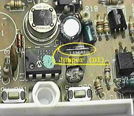
1. Remove the
batteries from the MS12A, remove the cover, and then remove the PCB.
2. Find and
Cut Jumper D1 in the MS12A
3. 
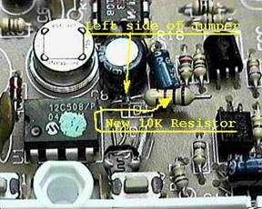
4. Add the 10K
Ohm resister to the LEFT side of the cut jumper D1
5. Next solder a wire on to the left side of the 10K resister and
route that to LUX RC Pin, then solder a wire from the right side of the 10K resister to V-, also cut the RC pin so it no longer make
contact with the LUX wall plate since you will not need that, that is only used
to tie to a normal central AC control
6. Next solder
a wire to the V+ on the MS12A, that is easy to find, just follow the red wire from
the battery area to the MS12A PCB. (If you want to be able the turn off the
MS12A control, and then run the power wire through the SPST Micro Switch before
going to the PCB, this will let you turn off power to the MS12A.
7. Next Solder
another wire to the V+ on the MS12A and then solder that to the 500K Ohm
Resister, from the other side of the resister, solder a wire to the resister
and route it to Pin Y on the LUX, as
with Pin RC, cut Pin Y on the LUX
for the same reason.
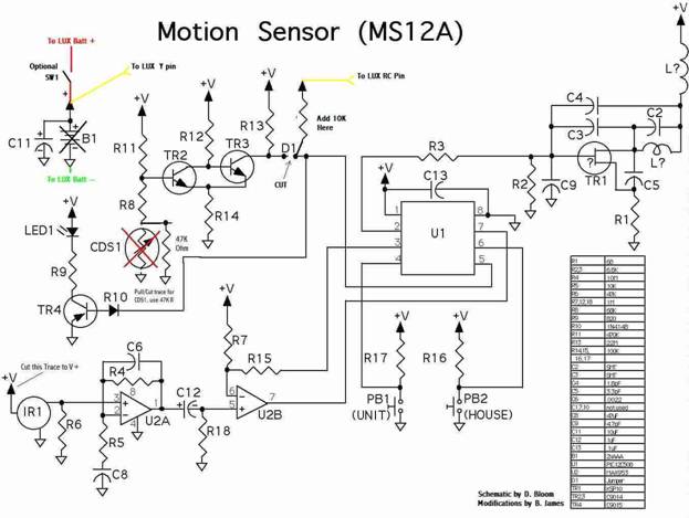
8. That is it
on the wiring, but there are 2 other things that are optional, refer to the
included schematic below for these mods. On is you can remove the Light Sensor
(CDS1) and replace it with a 47K Ohm resister, or optionally just put a piece
of black electrical tape over it. The other Mod is you can cut the PCB trace
that feeds power to the motion sensor (IR1), this will save power but again is
not really needed for power save but I was a purest so did it anyway, you can
optionally cover the motion sensor with a thick pad, like one of those little
stick on felt pads to keep from scratching tables. The last thing you want is
motion to get detected and trigger this…
9. Now look at
my picture for a good place to mount the MS12A PCB.
10. Use
double-sided stick ¼” foam tap pads for this to make sure nothing shorts out
when mounted.
11. Now put the
batteries in the LUX (2 AA) and program the MS12A per the instructions in the
manual to send the House and Unit Code you want to use. (Make sure if you added
the power switch in Step 6 that it is ON.)
12. You will
also need to bend over any parts standing too tall on the MS12A, just take care
doing this, there are a couple transistors, and a Cap you will want to bend
down so the LUX Control unit snaps on to the Wall Plate ok. Plug the LUX
TX-9000 in to its wall plate.
13. Next, Plug
in the TM571 with the House Code you have picked
14. Next, Set
the control module House and Unit code to what you picked the MS12A to send. Plug
in the Module you have picked to control in to the wall, in my case it was the
PAM04
15. Plug in
your device (Air Conditioner in my case) to your module, turn it on.
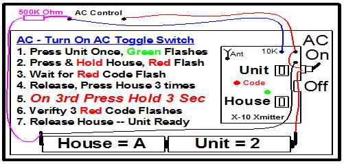
Testing
The X-10 Transmitter is mounted in the LUX TX-9000 case and
attached to +3VDC as shown. Then 3VDC from +V is routed through pins “Y” and
“RC” to R11, when the Air-Conditioning comes on +3VDC is sent to R11 as shown,
this sends one X-10 On command. When the contacts between “Y” and “RC” open,
the Transmitter sends one X-10 Off Command.
1. On the
TM751, Hit the ON/OFF button to ensure it turns your module on and off. If that
works you are now ready to see if you have the LUX and MS12A set-up right. Now
turn the TM751 off. (Remember with AC units you should wait a few minutes
before turning them on and off…)
2. Set the LUX
to Cool Mode
3. Turn down
the set point until the LUX “calls for AC” you will see the AC indicator in the
LUX LCD display, this should trigger the X-10 On Command and you’ll hear the
TM751 click, then the AC Unit will come on.
4. Wait a few
minutes and then Turn up the set point until the LUX stops calling for AC,
you will see the AC indicator in the LCD
display go out. Don’t worry if it lingers a minute or so the LUX thinks it is
controlling a central AC unit and usually runs for a minute or so when it’s
time to turn it off.
Schematic
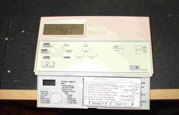
LUX Inside View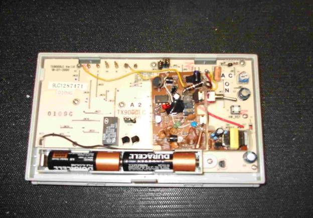
Settings Instructions
LUX Control
Cover Open
 LUX Finished
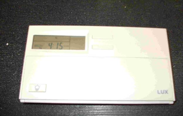
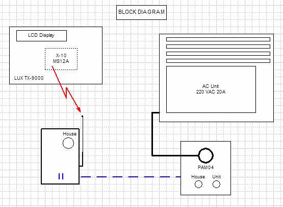
Block
Diagram
Final
Notes:
·
This obviously voids any warranty on the LUX and X-10
MS12A
·
There is no exposed high voltage, in the LUX when it
is not on the wall mount; 3VDC is the max you are exposed to.
·
Once it is mounted on the wall, there is 24VAC, but
you really can’t touch it since the LUX picks that up from the wall mount that
is wired to your heating system potentially, still not high voltage but take
care not to zap yourself when the wall plate is exposed.
·
You take
full responsibility for all aspects of this project.
·
Look at the web site I provided at the top, you may
prefer those modifications but take note, they are for DRY (no voltage) contact
control and in this case you have 3VDC running around on RC and Y, don’t fry
your MS12A using a dry contact design!
Prepared and
Designed by B. James with input from users on alt.electronics, X-10 Schematic,
D. Bloom (photo of MS12A) – May be copied and posted provided credits are
included. LUX & X-10 Retain all Patent and Copyrights to their devices. I
release any rights to the use, re-use of this X10/LUX project, it is free to
use! A link to a PDF Version is below and is easier to read