Stebel Horn Installation (Another Option)

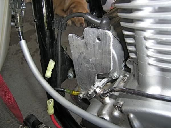
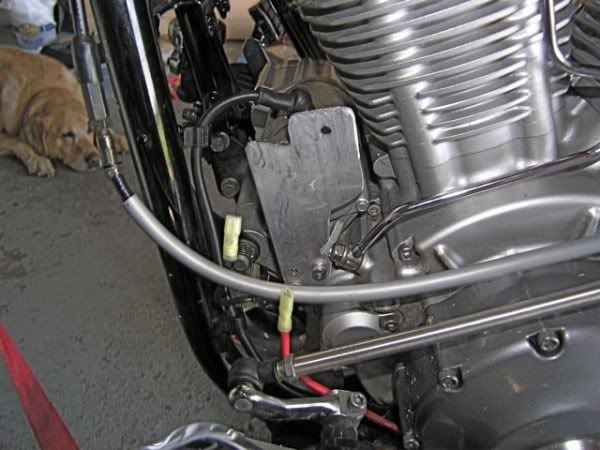
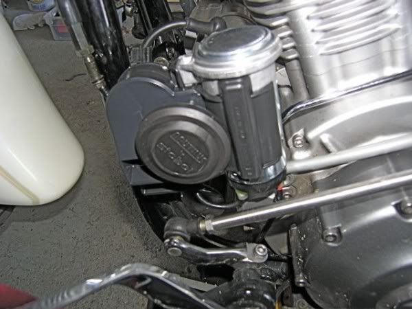
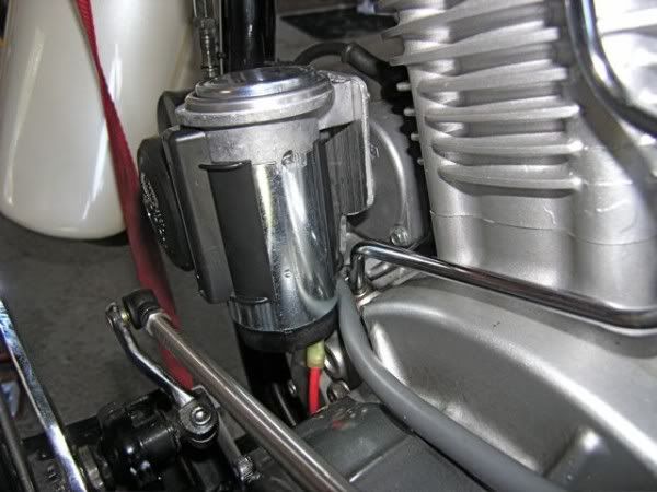
There are multiple ways and places to mount the Stebel Ear Blaster horn.  This is the way I installed it.  The instructions included with the horn state that the horn should be mounted vertically for proper drainage.  This install accomplishes that and I think it takes a minimal amount of space and is not too obvious.  

Stebel offer a chrome version but it didn’t look too good to me. The electrical connections are on the bottom.  I eliminated the front and rear stock horns, as this one is loud enough.

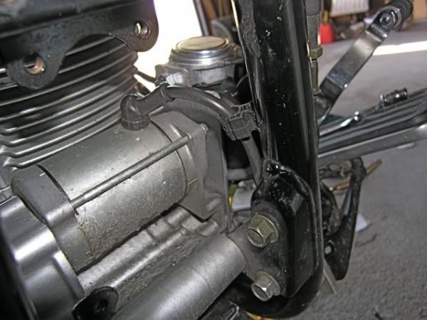
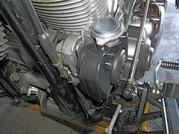
With this installation the bolt goes through the plate and can be loosened and tightened with an open end wrench for easy removal and installation.

stebel1edit.jpg picture by new_roadie

The plate was fabricated out of a piece of 3/16 aluminum.  I just cut and ground the shape to be minimal and to follow the shape of the backside of the horn.  I used the existing cap head screws as shown.  The ground wire for the horn is attached to one screw.  I later wrapped black electrical tape around the wire so it would blend in with the frame.

stebel2edit.jpg picture by new_roadie


stebel3edit.jpg picture by new_roadie


Below is the wiring diagram included with the Stebel, it shows the two stock horns still in place.  Keeping them is a personal choice.  The relay comes with the horn.


stebel4edit.jpg picture by new_roadie


Below is the spade identification pic for the relay.  Run a 14-gauge wire with a 15-amp fuse inline from the battery to the relay.  Then run a 14-gauge wire from the relay to the positive side of the horn.  I connected to the horn button wires in the wiring harness as it comes down the frame at the backside of the engine.

stebel5edit.jpg picture by new_roadie

Below are the completed connections just lying on top of the fuse box. 

stebel6edit.jpg picture by new_roadie


Below is the connection strapped to the frame and ready for button up.  The relay and the fuse are zip tied to the frame underneath the left side cover.
                                                           

stebel7edit.jpg picture by new_roadie


Below are more pics from the install.  I originally ran the clutch cable behind the horn and then when I changed to a SS braided cable I ran it below the horn.
                                                             

stebel8edit.jpg picture by new_roadie


Below is a pic from the backside of the horn.
                                                                      

stebel9edit.jpg picture by new_roadie


Below is a pic from the front and before I wrapped the wire with black electrical tape.  Black wire might be an option.


stebel10edit.jpg picture by new_roadie


Below is a pic from the top showing the clearance for the shift linkage.


stebel11edit.jpg picture by new_roadie


Good luck.  If you have any questions you may email me at:  jimwy@albanytel.com

Ride safe,

                 
Jim in Minnesota (Da Ice Man)