Picture A
Stebel Horn Mod
'
'
Two things are consistent with ALL Japanese manufactured motorcycles
that being cheap seats and wimpish
scooter horns. We all want a horn that gets immediate respect. The Stebel 'Nautilus' fits the bill perfectly.
This report details a bracket that I fabbed out of the stock mounting bracket for the front horn. It locates the stebel
to the right of the shifter and down low, almost to the frame. The horn ends up right near the front of the shifter bar
but there is no interference. It will require some time, patience and a trip to the hardware store but IMHO, it is worth
your time and effort to make this bracket and install the stebel horn.
Creating the bracket requires flattening the stock horn mount bracket, cutting it, filing, drilling, and painting it. Once complete,
the ONE hole you have drilled will be through bolted with a stainless bolt and washers. The horn is designed to mount securely
on this stud and is locked down with a stainless lock bolt.
Tools you will need:
Allen wrench to remove the two bolts securing the starter
A skill saw with metal/masonry blade.
Safety glasses and a ball pein hammer, also a chisel point
Electric drill and bit to match the mounting bolt diameter.
Sturdy block of wood. Elcheapo wire coat hanger
BLUE locktite and JB weld (quick or regular)
Vice Grips, needle nose, wire strippers, sharp knife.
Paint primer and HiTemp aluminum metallic spray paint. Small brush.
'
Parts to obtain:
ONE ¼ stainless steel bolt 1+1/4 inches long, a SS lock washer, SS locking nut, and
TWO regular SS nuts. Various electronic connectors for the job.
'
Get Started: I put my bike on a jackstand. It seems to make for easier access to things. Remove the front seat and the
front horn. Cut the TWO wires going to the horn flush with the connectors. Throw away the connectors. One of these wires
is PINK, the other BROWN. You will use these wires to trigger the horn relay. Instead of tapping into the wire stem near the
battery, I cut a wire coat hanger and used it as a fish tool to pull these two wires back up the channel behind the motor to
the battery area. Strip them and set them aside leaving them hanging. They should be right in front of the battery area.
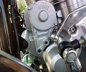
Remove BOTH mounting bolts from the starter, as depicted here in Picture A.
'
Picture A
'
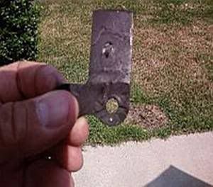
Time for bending, cutting and shaping: Use safety glasses at this point. I heated the bend in the bracket a bit with
a torch, but you could simply use a vice, if you have one, to bend the bracket flat. I heated the bend and then pounded it flat with
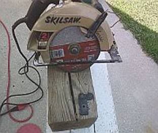
a ball pein hammer. The next step is to get that skill saw out and cut the bracket. Lots of sparks here, but it works. Cut as to leave
as much of the stem as possible. Picture B depicts the piece of the bracket that you will use.
' ...
...
Picture B
'
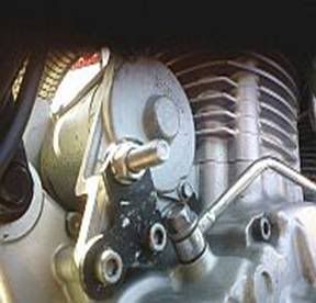
When it cools, spray paint it with primer and mount it onto the base of the starter with the starter bolts as depicted in Picture C.
' .....
.....
Picture C Picture D
'
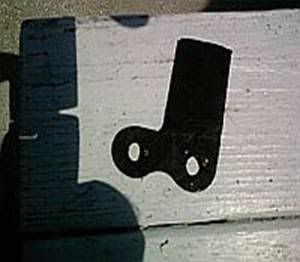
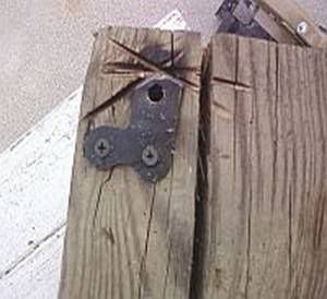
At this point, you will take the horn and bring it into the place where you would like it to mount on the bracket. Get your knife blade
and scratch out around the frame base and where you will drill the mounting hole. Picture D depicts the etched bracket removed.
I secured the bracket to a wood block with drywall screws, used a center punch to seed the drill bit then drilled it. The drywall screws
worked good to keep it secure. I also trimmed the bracket a bit with the saw and filed it down (both sides). This is depicted in Picture E.
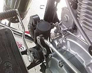
Now you will install the bolt with a lock washer then a nut. Tighten securely. You can now grind some off the base of the bolt if you're
clearance to the base of the starter mount is too tight. The bracket can now be mounted with the starter bolts as depicted in Picture F.
Be sure to use the blue locktite on the starter bolts.
' .....
.....
Picture E Picture F
'
At this point you can get the hi-temp metallic aluminum paint and paint the bracket to match the starter and engine. I used a small
brush and just sprayed some of the paint into a bottle cap, dabbing from that. Now you will stack the mounting stud by screwing
on a SS lock bolt (the ones with plastic inside). This point is tricky because you must REVERSE this bolt on the stud with the top going
on first. Screw it all the way to the base of the tightened bolt. You will now mix up a bit of the JB weld (JB quick will work great here)
and put some at the tip of the stud and coat about 3 or four of the threads. Now just screw on the last SS bolt and wait for the weld
to setup. The locking bolt you threaded on earlier will lock the horn onto the stud. The welded bolt will be inside the horn mount.
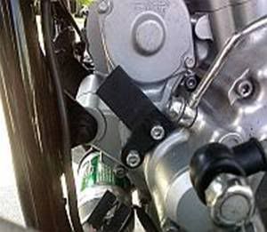
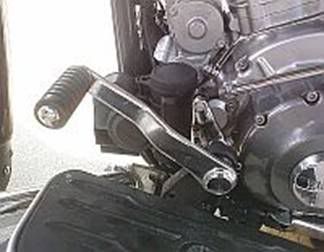
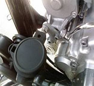
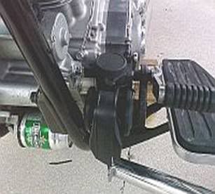
Below are pictures of the completed horn after painting with flat black. It is out of the way, secure, and the shifter does not hit it
though it comes close. You can adjust the shifter to compensate if you made a mistake.
' ....
....
' ....
....
'
Wiring the horn is easy. The BROWN wire is positive and would go to terminal 86 on the relay. The PINK goes to terminal 85 but it is
no big deal if you get them reversed. The relay will still work to send current to the horn. The hot wire with fusible link will go to terminal
30 and terminal 87 will connect to the POSITIVE terminal of the horn via a wire run down the wire trunkline and inside the left frame
rail past the kickstand to the horn. I grounded the horn (negative terminal on horn) to one of the holes where the OEM horn mount
bracket was and this produced a good ground connection. If the horn does not work full blast, it is probably because your ground
connection is not good. There is ample room under the side cover to place the relay and fuse holder.
'
I like this mounting option because the base of the horn where the connectors are is protected from the elements by the floorboard
mount assembly and the horn is completely vertical, as the directions call for. That SS lock bolt on the stud must be torqued tight
(someone said 50lbs) in order to keep the horn secured no matter what mounting system you use.
'
JETJKY